Sunday, December 5, 2010

PID Velocity Motor Controller Code Breakdown

In the previous PID Velocity Motor Controller post I discussed the project hardware and project goals. In this post I want to share some breakdown of the PID code as it stands today.

The following code examples are for Atmel AVR microprocessors using the gcc-avr compiler and tool chain.

Encoder Structure:
 typedef struct{    
   int direction;    // Encoder rotation direction.  
   int count;        // Encoder count.  
 } encoder, *pencoder;  
   
 encoder REncoder;  
 encoder LEncoder;  

Motor Structure:
typedef struct{  
   float kp;                // Proportional gain  
   float ki;                // Intigral gain  
   float kd;                // Dirivitive gain  
   float velocity_setpoint; // Motor velocity setpoint in encoder counts per control loop  
   float velocity;          // Motor velocity in encoder counts per control loop  
   float previous_error;    // Motor's previous proportional error  
   float integral_error;    // Motor's integral error  
 } motor, *pmotor;  
   
 motor RMotor;  
 motor LMotor;

Saturday, December 4, 2010

PID Velocity Motor Controller

Over the last few days I have been working on a simple PID velocity DC motor controller that will be my entry to the Trossen Robotics contest. While it is not a project that is new or novel I feel that documenting and sharing the creation of the full system from top to bottom better fits the contest's judging criteria.

This post will serve as an update on the progress I have made on the project thus far.

My setup for development consists of a MINI robocontroller from Vanadium Labs, DC Gearmotor from Pololu and wheels from BaneBots. The MINI robocontroller is simply being used as a convenience at the moment allowing me to focus on software rather then hardware. I will be replacing it with a custom PCB in the near future.

PID Controller Development Setup

Saturday, November 20, 2010

Fractal Terrain Generation Using The Diamond-Square Algorithm

Continuing on with my experimentation with the fractal mountain range and Mandelbrot set I have set my eyes on generating a 3d fractal landscape with ambitions of moving onto a fractal planet.

 I have been tinkering with the Pyglet python library. Pyglet is a wrapper for the OpenGL (Open Graphics Library).

Shown below is my attempts at visualizing the result of a terrain generated from the diamod-square algorithm

First attempt. Has some obvious algorithm errors.

 Second attempt with a revised algorithm.


You can download the python code here.

Thursday, November 18, 2010

Generating A Fractal Mountain Range

I stumbled across this page about generating random fractal terrain. I went ahead and made a simple wxpython app to put the ideas I learned into practice. Below is the result and source code.


Wednesday, November 17, 2010

Gold Rush Turret Taking Shape

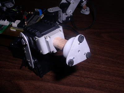
Work continues again on Gold Rush's mechanical aspects after a long period of working on electronics and software. My focus has been on creating a robust turret with pan and tilt capability that mounts the Trendnet IP camera and dual Matyo Toy tank guns.


The goal over the next few weeks is to continue to mount all of the required Mech Warfare gear. Once all everything is mounted I can shift focus over towards tuning the walking gaits can remote control.

Saturday, November 13, 2010

Using Python To Draw The Mandelbrot Set

I recently watched a documentary on the discovery of the Mandelbrot Set on youtube and it sparked my curiosity. I went ahead and made a little python app that draws the famous Mandelbrot set in a wxpython window. You can see the result of my work and the source code below. It is by no means useful or elegant code but it was a fun exercise!


Tuesday, November 9, 2010

Friday, October 15, 2010

Mato Toys Tank Gun Modification

I purchased a few 'Tank Guns' from Mato Toys that some of the other Mech Warfare guys have used in the past. These are designed to be used in remote control model tanks which is apparently a popular hobby in some parts of the world.

This gun is much smaller and lighter then the airsoft gun I used on Second Amendment but its firing rate is extremely slow and disappointing. Another competitor at the Mech Warfare 2010 event had modified this same gun for a faster firing rate so I set out to discover the modification myself.


Here is the Tank Gun in all its cheapness glory. It is a slightly different form factor from Mato Toys product image but everything important seems to be the same.


Here I have removed the motor and one side of the gun's casing. We can see the inner workings of the gun. It works almost identical to the spring airsoft gun I used on Second Amendment. This gun uses a much smaller motor with many gear reductions to pull back the gun's spring/plunger.


Here is a picture of the modification I made. Normally the pinion is press fit onto the end of the motors shaft. I simply tapped the pinion down the base of the shaft. By repositioning the pinion like this it is simply bypassing two of the gear train's gear reductions increasing the guns firing rate.

The modification couldn't be simpler and was immediately obvious once I opened up the gun. Any negative long term affects on the motor or gear train is still unknown and requires some testing. Use at your own risk.

Tuesday, October 5, 2010

Prototyping an ATMEGA168 And Xbee Based Robot Controller

I have recently started work prototyping some ideas for a simple wireless remote controller for my robots.

Originally I was going to purchase some thumb joysticks available from Sparkfun to use for prototyping. Luckily I had the idea to use an old Playstation One Dual Shock controller that has been collecting dust for ages in my closet. It was kind enough to donate its innards for my purposes. Surprisingly the thumb sticks found inside the Playstaion controller are identical to the Sparkfun ones.

I went ahead and etched two breakout boards for the liberated thumb joysticks and have begun to interface them with one of my ATMEGA168 breakout boards. The software is really quite simplistic. It is just a matter of doing two analog to digital conversions for each axis of the joystick, forming a packet with the joystick readings and transmitting the packet out the micro's USART to the Xbee module.

Sunday, September 19, 2010

Determining Encoder Rotational Direction Using An ATMEGA168


While working on a DC motor controller project I needed to decode quadrature encoder signals.

Basically a quadrature encoder has two signal lines, A and B. Rotational direction of the encoder can be determined by the phase difference between these signals. 

A simple way to detect the phase difference of the signals with the ATMEGA168 is to generate an interrupt on the falling edge of signal A and look at the value of signal B. If signal B is high of the falling edge of signal A the encoder is turning one way. And if signal B is low on the falling edge of signal A the encoder is turning the other way.


Wednesday, September 15, 2010

AVR PWM Signal Generation Using The ATMEGA644P's Timer


While working on a recent project I needed to generate a PWM signal from my ATMEGA644P in order to operate a SN754410 motor driver as a speed controller.

To generate the PWM I used the ATMEGA's 8-bit Timer/Counter 2 configured for fast PWM mode. Fast PWM works as follows:

The timer will continually count up from 'bottom' to 'top'. When 'top' is reached the counter will then wrap around and begin counting up from 'bottom' again. In this case we are using an 8 bit timer so 'bottom' will be equal to 0 and top will be equal to 255 decimal or FF hex. When the counter reaches the 'compare' value an output pin will be set. This pin will then reset when the counter wraps around to 'bottom'. We are able to vary the value of 'compare' in order to generate a fixed frequency PWM signal with a variable duty cycle.


In order to set up the timer its registers need to be configured as follows:

Set the Data direction for timer pin set as output
I am using timer 2 output A so pin 7 port D (PD7 OC2A/PCINT31) needs to be set as output:
DDRD |= (1 << PD7)

Set waveform generation mode
Waveform generation mode is set in the two registers TCCR2A and TCCR2B, Timer/Counter Control Registers A and B. I need Fast PWM counting from 0 to 0xFF so I set the registers as:
TCCR2A |= (1 << WGM0)
TCCR2A |= (1 << WGM1)

Set compare output mode
Compare output mode is set in the TCCR2A register:
TCCR2A |= (1 << COM2A0)
TCCR2A |= (1 << COM2A1)

Clock selection
Clock selection is set in the TCCR2B register. I am not concerned about the frequency of the PWM signal so I just select the AVR's clock as without any prescalling.
TCCR2B |= (1 << CS20)

Set the output compare
Lastly the fast PWM's duty cycle needs to be set by adjusting the compare value. This is set in the OCR2A, Output Compare Register A. This register can be written to in any point in software to vary the duty cycle of the output PWM signal.
OCR2A = duty_cycle

Friday, September 10, 2010

Sunday, September 5, 2010

Trossen Robotics DIY Project Contest!

Trossen Robotics is holding a DIY project contest with some great prizes.


I plan to enter the contest with a new project that I will be documenting here on the blog. For more info on the contest check out Trossen Robotics Project Contest Page.

Wednesday, August 25, 2010

Feets!


Friday, August 20, 2010

Gold Rush Online - Ripple and Amble Gait Walking

I have temporarily mounted all of Gold Rush's electronics to the top of his chassis so I could start testing his walking.


Monday, August 2, 2010

Gold Rush Serial Data Packet Control

Over the last week I have been able to get wireless control working with my AVR micro. Communication to the AVR is being done by sending wireless serial data packets using xbee modules.
At the moment my packets consist of two header bytes (0xff) to designate the start of a new packet. The header is then followed with 4 bytes to hold the values of 2 joystick (horizontal and vertical axis). The packet is then ended with a checksum.

I have created a simple python and wxpython app to simulate the control of two joysticks using some slider widgets. This app simply reads the value of the 4 sliders, forms a data packet and writes it out serially to a xbee module connected to my PC around 30 times a second.


MechController.py demo window.

On the micro side I have a second xbee module connected to one of the atmega644's usarts. The micro is adding every byte it receives on this usart to a ring buffer. Then, when called, a function is able to search this buffer for a full data packet, pull out the joystick data and flush the buffer.

Here is a little video I took to demonstrate it all working. Off camera I am changing the values on the top two sliders in my python app. These two sliders represent the vertical and horizontal axis of a single joystick. In turn the value of each slider determines the walking direction of the robot.

Sunday, July 25, 2010

AVR Wireless Serial Communication

Progress continues with my AVR microcontroller board...
Today I was able to get some simple wireless serial communication tests working.


I followed this great tutorial post on AVR Freaks on creating interrupt driven USART echo program. I then took it a step farther and had each side of the serial link (PC and micro) echo the last character received pulse one.

All in all the test were not very interesting but they do lay groundwork for the development of a control packet structure for driving Gold Rush around.

Thursday, July 22, 2010

AVR Dynamixel AX-12 Controller Running IK and Gait Engine

I was able to get my IK functions and gait engine running on my AVR micro.

Below is a short video of the front left leg running an 8 step ripple gait in the forward direction.

Wednesday, July 21, 2010

AVR Dynamixel AX-12 Controller

Over the last few days I have been working on my AVR microcontroller board that I posted about a while back.

So far I have been able to implement the Dynamixel AX-12 communication protocol and have successfully commanded an AX-12 servo.

I am now in the process of porting over my IK and gait engine from python running on my PC to C on the micro.


As always you can download my code here.

Friday, July 2, 2010

IPMechCam Progress

Work continues on the on IPMechCam.

I have been trickling some smaller updates in the IPMechCam thread in the Trossen Robotics Community forums. This post will serve as a wrap up of all the major updates.

Testing IPMechCam text widget and widget preferences.

IPMechCam has been rolled into a larger software package I am working on for walking robots by the name of UpgraydMech. As of today the only Upgrayd Mech tool available for testing is IPMechCam however. 

Four screen widgets are available with a few more in the works. A text widget allows the display of a label along with a value as text. A graph widget displays a value over time in an XY graph. A color scale widget presents a value as a graphical representation similar to a temperature scale. And the simple cross hair widget for gun targeting.

Widget preference settings have had the most improvements. The widgets preferences dialog allows for the creation individual widget instances. It also provides a nice interface for adjusting all the properties of the widgets, managing widget instances, and soon allow the saving and loading of widget settings.

Widgets are able to pull values out of a data stream. This data stream can be accessed by other UpgraydMech tools, robot controllers and robot systems. (Arbotix support? MechWarfare scoring system?)

If you would like to try IPMechCam:
  1. Download and install Python (either version 2.5 or 2.6 is fine. I use 2.6)
  2. Download and install wxPython GUI toolkit library.
  3. Download the current version of UpgraydMech.
  4. Unzip and run the UpgraydMech.py file.

Saturday, June 12, 2010

Gold Rush Leg Parts and Brackets

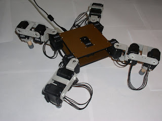
I got to work on Gold Rush and completely replaced all the stock bioloid brackets used for the legs. All parts were machined from 0.06 inch thick aluminum sheet on a manual vertical mill, bent with a metal brake and media blasted.

Servo horn, servo body brackets and femur cross supports.

Coxa and Femur leg segments assembled.

Servo body brackets to foot mounts assembled.

Servo body brackets and foot mounts attached to leg.

Wooden dowel feet added and legs fully assembled.

Monday, May 31, 2010

Gold Rush's Walking Gaits

I have uploaded two videos of walking gaits that I have been working on for Gold Rush.

First up is a video of an eight step ripple gait:


This video showcases an amble gait as well as a feature that allows the robot change walking gaits on the fly:

Second Amendment OverHaulin'

I have started work on a new Mech, Gold Rush, but that does not mean Second Amendment will be retired.

An overhaul of SA's chassis is first up on the list of improvements. It will be replaced by a more traditional 'sandwich' style chassis that will have less parts and be lighter.

I want the legs to remain the same so I have created some brackets to easily adapt SA's old legs to a new chassis.


I am also in the process of designing a new turret that will be used on both SA 2 and my new mech Gold Rush.

All other components of SA will remain the same.

Introducing GoldRush A New Quad Mech

A while back I posted about joining the dark side and acquiring a set of AX-12 Dynamixel servos.

The servos are going to be used in a new quad mech for the next Mech Warfare competition.

Wednesday, May 19, 2010

Joining The Dark Side

Or at least that is what they call it over in the Trossen Robotics community...


I have acquired a set of 14 Dynamixel AX-12 servos by Robotis along with Bioloid Bus Interface board by HUV Robotics to allow easy PC to AX-12 bus communication.

Thursday, May 13, 2010

Wednesday, May 12, 2010

IPMechCam HUD Widgets Demo

IPMechCam Features in Progress List

Just wanted to share a list of features for IPMechCam I am currently working towards and their priorities:
  • H - Camera Configuration Dialog (Change IP, username and password without needing to dig into the code)
  • H - Global Widget Color (Color picker w/ preview to set color of all HUD widgets)
  • L - Local Widget Color (Ability to override the global color setting for individual widgets)
  • H - Save and load widget, camera and video preferences (Preferences can be saved to a text file. Preferences are loaded on program startup)
  • M - Screen size scaling (Adjust the frame size and have the camera image and widgets scale accordingly)
  • L - Keyboard hot keys

I have already made some progress with a color picking interface...
At the moment you can mix red, green, and blue to get your desired color. I am also planning to add a control to adjust the color alpha to hopefully allow semitransparent widgets. Having the option of text input would also be nice if a user knows what color they want.

Monday, May 10, 2010

Introducing IPMechCam

IPMechCam is a cross platform python program to display a motion jpeg stream from an IP camera. The intent is to provide a powerful, customizable and easy to use application for anyone to use in the Mech Warfare robotics competition.

By default IPMechCam will support the TRENDnet TV-IP100W camera with the option to expand support for other similar IP cameras.

The most interesting feature of IPMechCam will be its support for highly customizable HUD or Heads Up Display widgets. HUD widgets are able to display information in a visual manner over the top of IPMechCam's camera image. Information can include cross hairs to indicate targeting, sensor and control status relayed back from the mech and even indication of game status such as time remaining in the match and the current health of both you and your opponent.

IPMechCam is the first tool in a line of applications geared for the Mech Warfare robotic competition. Other tools planned include gait visualization and optimization, gait generation, pose/sequence editor and robot control interface.

Current progress can already be viewed in this thread of the Trossen Robotics community forums.

Thursday, March 25, 2010

Friday, March 19, 2010

AVR Digital I/O Registers

Each port pin consists of three register bits: DDxn, PORTxn, PINxn.
DDxn bits are accessed at the DDRx I/O address.
PORTxn bits are at the PORTx I/O address.
PINxn bits at the PIN I/O address.

Note:
Each instance of 'x' should be replaced with the port identification letter (A,B,C,D, ect.)
Each instance of 'n' should be replaced with a pin number (0..7)

DDRx is the Data Direction Register. This register sets the data direction of individual pins of port x. A logic level of '1' sets a port pin as output. A logic level of '0' sets a port pin as input.

ex:
DDRB=0b00000001 // Set direction of port B pin 0 as output, all others input
DDRD=0b00100010 // Set direction of port D pin 5 and pin 1 as output, all others input

PORTx is the Data Register. If you have set any pins on the port as output using the DDRx register you can now control them with this register. A logic level of '1' makes a port pin high. A log level of '0' makes a port pin low.

ex:
PORTB=0b00000100 // Make port B pin 2 high, all others low
PORTA=0b00000101 // Make port A pin 2 and pin 0 high, all others low

PINx is the Input Pin Address Register. If you have set any pins on the port as input using the DDRx register you can now read the status of them with this register.

ex: Assuming a switch is interfaced to Port A Pin 0 with a pull up resistor...
if (PINA & 0b00000001) {
    // Switch interfaced to Port A Pin 0 is open
}
else {
    // Switch interfaced to Port A Pin 0 is closed
}

Thursday, March 18, 2010

Prototype ATmega644P Breakout Board First Program

Loaded up my first program to my ATmega644P board today. Its just a simple program to set Pin 0 on port B as output and then loop forever toggling the the pin as high and low with a short delay in between.

Board setup and scope output.

The code is not so interesting so I wont bother posting it here. Its nothing that can not be seen in any other beginner tutorials for AVR micros around the net.

I will be doing some experimenting with the Analog-to-digital converter and dual USART ports on the ATmega644P that will probably be a bit more interesting.

Wednesday, March 17, 2010

Programming an ATmega644p with AVR Studio and the AVRISP mkII

Target:
ATmega644p

Programmer:
AVRISP mkII

Platform:
Windows 7

Software:
AVR Studio Version 4.18
AVR Studio 4.18 SP2 (build 700)
WinAVR

Pinouts:
pin 10(VCC) and 30(AVCC) are +5v
pin 11 and 31 are GND
pin 9(RESET) pulled high with a 10k Ohm resistor

pin 6(MOSI) to ISP pin 4
pin 7(MISO) to ISP pin 1
pin 8(SCK) to ISP pin 3
pin 9(RESET) to ISP pin 5

Tuesday, March 16, 2010

Monday, March 15, 2010

Sunday, March 14, 2010

5V Fixed Voltage Regulator and Ripple Voltage

I have been experimenting with the common 7805 linear voltage regulator as a power supply.

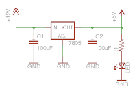
To start I simply wired up the regulator with an resistor and led as the load.

Looking at the output of the regulator on my scope we can see a large ripple voltage of around +/- 1 volt!

I would prefer a nice and clean clean 5 volt output and in order to provide it we need to smooth out the supply voltage. Adding some larger capacitors on both the input and output of the regulator reduces the ripple we see above.

Two 100uF caps are added from input to ground and output to ground.

The result is a clean 5 volt output.

I picked the two 100uF caps because thats just what I had handy. Intuition tells me that larger caps will take longer to respond to the ripple voltage and that capacitors that are too small will not hold a charge large enough to compensate for the ripple. I do not know is how to determine optimally sized caps.

Also I really did not have a load on the output of the regulator. I am curious of the effect of a larger current draw in the circuit.

Thursday, March 11, 2010

SA Improvements Underway

Attending the CIRC Bot Brawl was a great proving ground for SA. Myself and the Mech Warefare participants in attendance learned a lot.

A few things that I observed:

Circuit protection
SA's camera and transponder are unprotected from stray bbs.

Gun Wiring
Wiring is a mess up on the turret. Will need to look into some better wire management.

Turret Mechanical Limits
Turret unable to aim down making it impossible to shoot low mounted targets on close mechs.

Fine Turret Control
My fine turret control needs to be finer. Will make aiming much easier.

Small Camera Image
The camera image on the drivers end is much too small. Needs to be full screen.

Large Step Length
Need a larger gradient on step length. Will make positioning and aiming easier.

Ugly Target Panels
Would like to dress these up to match the robot. Possibly add some Upgrayd Labs logos or some kind of made up paramilitary decal.

CIRC Bot Brawl Recap


On March 6th, 2010 SA and I attended the CIRC Bot Brawl event in Peoria Illinois.

The event was for competitions sponsored by the CIRC group. They had light weight combat robots (1-3 lb I believe), line following, sumo and other typical robot competitions. Between CIRC events Mech Warefare demos were held to gain interest in the competition.

Four mechs were in attendance. Two quads (SA and Issy) along with two Lynxmotion Biped BRAT based mechs. Unfortunately only the two quad mechs were fully functional and able to run a few demo skirmishes. One Biped BRAT was experiencing some electrical interference issues between his own electronics while the other was unable to keep balanced with all the required Mech Warfare gear attached.

Friday, February 26, 2010

Using Python and Pygame to Display A Motion JPEG From the TRENDnet Wireless Internet Camera

1:  import time  
2:  import httplib  
3:  import base64  
4:  import StringIO  
5:  import pygame  
6:  from pygame.locals import *  
7:    
8:  class trendnet:  
9:    
10:      def __init__(self, ip, username='admin', password='admin'):  
11:    
12:          self.ip = ip  
13:          self.username = username  
14:          self.password = password  
15:          self.base64string = base64.encodestring('%s:%s' % (username, password))[:-1]  
16:    
17:      def connect(self):  
18:    
19:          h = httplib.HTTP(self.ip)  
20:          h.putrequest('GET','/cgi/mjpg/mjpeg.cgi')  
21:          h.putheader('Authorization', 'Basic %s' % self.base64string)  
22:          h.endheaders()  
23:          errcode, errmsg, headers = h.getreply()  
24:          self.file = h.getfile()  
25:    
26:      def update(self, window, size, offset):          
27:            
28:          data = self.file.readline()  
29:          if data[0:15] == 'Content-Length:':  
30:              count = int(data[16:])  
31:              s = self.file.read(count)      
32:              while s[0] != chr(0xff):  
33:                  s = s[1:]       
34:                    
35:              p = StringIO.StringIO(s)  
36:                
37:              try:  
38:                  campanel = pygame.image.load(p).convert()  
39:                  campanel = pygame.transform.scale(campanel, size)  
40:                  window.blit(campanel, offset)  
41:            
42:              except Exception, x:  
43:                  print x  
44:                    
45:              p.close()  
46:                
47:  if __name__ == '__main__':  
48:    
49:    pygame.init()  
50:    screen = pygame.display.set_mode((660,500), 0, 32)  
51:      
52:    pygame.display.set_caption('trendnet.py')  
53:      
54:    background = pygame.Surface((660,500))  
55:    background.fill(pygame.Color('#E8E8E8'))  
56:    screen.blit(background, (0,0))  
57:      
58:    camera = trendnet('192.168.1.103', 'admin', 'admin')  
59:    camera.connect()  
60:      
61:    while True:  
62:      
63:      camera.update(screen, (640,480), (10,10))  
64:      pygame.display.update()  
65:      
66:      for event in pygame.event.get():  
67:        if event.type == QUIT:  
68:          sys.exit(0)  
69:            
70:      time.sleep(.01)  

download code

Sunday, February 21, 2010

Pairing Xbee Wireless Modules


Xbee wireless modules offer a quick, easy and inexpensive way to provide wireless end-point connectivity in your projects.

While they do offer “no configuration needed for out-of-the-box RF communications” you will want to do some configuration to allow high speed communications with automatic resending of lost packets.

The easiest way to set the parameters of an Xbee modules is with the use of Digi's X-CTU software utility. X-CTU is a windows-based application designed to interact with Digi's RF products providing a simple GUI for firmware configuration.

For paring a set of 2 Xbee Modules the parameters we are concerned about are PANID (ATID), Destination Address Low (ATDL), 16-bit Source Address (ATMY) and Interface Data Rate (ATBD).

The PANID (ATID) or Personal Area Network ID is a number shared amongst each Xbee module in a network. Many Xbee modules could exist in the same area but only those that share a PANID can talk to each other. The default PANID is 3332 and should be avoided

The Destination Address Low (ATDL) sets the destination address of the Xbee module and the Source Address (ATMY) sets the address number of the Xbee module. For a pair of Xbee modules these should be set opposite of each other to enable automatic resending of lost packets.

The Data Rate (ATBD) or baud rate is the number of bits per second the Xbee module will send. Xbee modules must have matching baud rates for them to talk to each other. The default is 9600bps.

At the moment SA's Xbee modules are set to:

Xbee #1 – Computer Side
ATID = 4321
ATDL = 11
ATMY = 10
ATBD = 3 (9600bps)

Xbee #2 – Robot Side
ATID = 4321
ATDL = 10
ATMY = 11
ATBD = 3 (9600bps)

So far this configuration has been working well. I do plan to experiment with a higher baud rate soon as 9600bps is a bit slow. But for now all seems well.

Friday, February 19, 2010

Kodak Zi8 Pocket Video Camera

I have been in the market for a decent camcorder for a while now. All my previous video work has been through the built in iSight web cam built into my MacBook. Obviously that was not an idea setup. Poor quality vido, poor audio and awkward positioning being the main issues.

I wanted something that was small sized and portable, did not require a lot of gear, decent indoor video quality, and in the 200 dollar price range. The three cameras that fit these requirements included the Flip MinoHD, Creative Vado HD and the Kodak Zi8

Hands down the Kodak Zi8 really stands above the rest. Features including:
- 1080p video with 16:9 aspect ratio
- SD card slot
- External microphone jack
- Image stabilization
- Removable battery

I have uploaded a short test video to YouTube of SA walking that I took with the Zi8.


I plan to use this camera to keep this blog updated with my progress on Second Amendment, offer some coverage of the events I attend, generate some how-to and project videos and document any projects Team Upgrayd works on in the future.

Monday, February 15, 2010

Attending the CIRC Bot Brawl

On March 6th the Central Illinois Robotics Club will be hosting a robotics competition event.

Competitions at the event will include various sumo divisions, autonomous line flowing, autonomous maze completion, combat robots (1lb and 3lb divisions), best in show, and a few short Mech Warfare demonstrations.

I plan on attending and bringing along Second Amendment my quad mech to participate in the Mech Warfare demos. Also I will probably enter SA into the best in show competition. The focus of my best in show entry will be around inverse kinematics and walking gait sequences.

Date - March 6, 2010
Location - Lakeview Museum, Peoria, IL
CIRC Homepage
Bot Brawl 2010 Information

Improved Quad Walking Gait Sequence

Second Amendment's gait was functional and that is about it. It was clunky, mechanical looking and inefficient.

SA's gait was very simplistic. Basically alternating diagonal sets of legs would be raised and moved. While this works it is sloppy and prone to wondering (unable to walk in straight lines). Also, due to program structure, SA was unable to both walk and turn at the same time. These things had to be improved!

Enter the ripple gait. SA is now programed with an eight step ripple gait (leg up and forward, leg down, move body forward 6x). In addition it is now possible for him to turn while walking opening a great amount of possible body translations.

Monday, February 8, 2010

SA Shaping Up

Second Amendment is really coming together.


Just a quick rundown of everything that has happened from the last update:
Revised leg configuration
Test gun mount idea
Test ammo hopper
majority of mechanical components painted
optimized walk sequences
and more!