A few years ago my father built a neat little desktop CNC machine capable of engraving plastic and cutting thin materail with a Dremel tool.
As with most DIY CNC machines the control of its steppers relied on a computer with a parallel port. Obviously this is an issue for people who like to use modern computers!
I have decided to tinker with the machine. The plan is to program an AVR micro controller to interpret G-Code fed to it over USB or read from an SD card. The setup would be nearly identical to the controls of a reprap 3d printer.
In the embed video you can see how I have programmed an ATMEG168 micro controller interfaced with a Pololu A4988 Stepper Driver to drive the Y axis of the desktop CNC into a micro switch endstop.
I am not sure how far ill take this project but it sure is fun to play with different things.
Saturday, December 31, 2011
Sunday, November 6, 2011
9DOF IMU Development For Dynamixel Based Robots - Part 1
 I recently purchased the 9 Degrees of Freedom - Razor IMU from Sparkfun Electronics.
 My intentions with this device is to use it as a platform to start the development of an IMU that communicates on the Dynamixel AX (and/or RX /EX) buss for easy use in Dynamixel based robots.
Using Digi's X-CTU Application Under Linux To Configure Xbee Modems
Digi's X-CTU application is for configuring and testing Xbee modems. It works great but is windows only.
While rebooting into windows just to configure an xbee was a pain it worked. But this is no longer an option now that I no longer keep a windows installation on my machine. I needed a solution!
While rebooting into windows just to configure an xbee was a pain it worked. But this is no longer an option now that I no longer keep a windows installation on my machine. I needed a solution!
Tuesday, September 6, 2011
AX12 Darwin Walking Tuner
I made a sturdy stand for the robot that allows me to work on the movement without having to worry about it taking a tumble.
I have also started to work on a program that lets me fiddle with all of the walking parameters while the movement and IK engine are both running. Took a short video of me testing it out.
I have also started to work on a program that lets me fiddle with all of the walking parameters while the movement and IK engine are both running. Took a short video of me testing it out.
Sunday, August 28, 2011


Saturday, August 27, 2011
Friday, August 26, 2011
AX12 Darwin Update
After quite a few weeks I am finally getting back into this project.
Over the week I have finished most of the mechanical parts except the feet and a few arm pieces. This weekend I will be working on wiring up the servos and hopefully start to tune the the gait motions that up until now has only worked in simulations.

Over the week I have finished most of the mechanical parts except the feet and a few arm pieces. This weekend I will be working on wiring up the servos and hopefully start to tune the the gait motions that up until now has only worked in simulations.

Saturday, June 18, 2011
Sunday, May 22, 2011
Biped Robot Leg Prototyping
Heavily inspired by the Darwin OP robot by from Robotis and RoMeLa at Virginia Tech I have started A biped robot project.
So far I have constructed a prototype leg and have begun developing the software while finalising the mechancial aspects of the robot. The prototype leg design I am working with is a copy of the stock Bioloid Premium Type A configuration as seen below.

In this video I am demonstrating a simple pose, capture and playback program to test the range of motion in the leg and to make sure everything moves as expected. The program asks the user to pose the leg into two positions. Then does some simple linear interpolation between the poses, looping forever.
In the next video I have a test program that demonstrates the inverse kinematics algorithm I have developed for the leg. In this program I am able to enter 4 values (x,y,z,rotation) to position the center of the foot in relation to what would be the center of the robot.
AX-12 Monitor
AX-12 Monitor is a simple terminal program I am working on to interact with Dynamixel AX-12 Robot Actuator bus.
This program is still very much a work in progress but I plan on making the source along with a little bit of documentation available when it is finished.
Overo Gumstix Computer on Module
I have recently picked and begun experimenting with an Gumstix Overo Air COM (Computer on Module).
These interesting little computers are based on the ARM Cortex-A8 OMAP3503 Processor. The Air model that I chose to work with includes both 802.11g and Bluetooth wireless communication.
In the image below you can see the Gumstix Air booted from a micro sd card with and image of Linux version 2.6.36 and the GNOME desktop. This image also includes native development tools for c, c++ and python.

If all goes well I plan on using this single board computer in my future robotics projects.
Sunday, March 27, 2011
Python Hermite Curve Calculation And Display
A Hermite curve defines a unique path between two points based off of two control tangents.
I put together a little python program to play around with the calculation of Hermite curves to make sure I understood them before attempting to use it in other applications.

I put together a little python program to play around with the calculation of Hermite curves to make sure I understood them before attempting to use it in other applications.

Sunday, March 13, 2011
Logitech Dual Action USB Gamepad Interface Using Python
You can get a list of all input device files on your machine by using the command 'ls /dev/input'. My Logitech gamepad is showing up as 'js0'.

Using the cat command on the gamepad's device file 'cat /dev/input/js0' and then pressing some buttons on the game pad spews out a bunch of garbage in the terminal. This lets me know the gamepad is working but I am going to have to do a bit of programming to make some sense of all this gibberish.

Using python we can open and read the device pipe as if it were a normal file and print it in a slightly more readable format.

By observing the output of the simple python program I notice that each event on the gamepad (button down, button up, axis movement) produces 8 bytes of data. I then went on to modify the program to assemble the incoming data into eight byte messages and print each message to the screen.

By observing the data in this format I am able to determine a few things:

From here I am just a hop, skip, and a jump away from wrapping this into a class and saving the state of the buttons and axis into some sort of easily used data structures. I will be posting a follow up post when I get this concept into a usable format.

Using the cat command on the gamepad's device file 'cat /dev/input/js0' and then pressing some buttons on the game pad spews out a bunch of garbage in the terminal. This lets me know the gamepad is working but I am going to have to do a bit of programming to make some sense of all this gibberish.

Using python we can open and read the device pipe as if it were a normal file and print it in a slightly more readable format.
import sys

# Open the js0 device as if it were a file in read mode.
pipe = open('/dev/input/js0', 'r')

# Loop forever.
while 1:

    # For each character read from the /dev/input/js0 pipe...
    for char in pipe.read(1):

        # write to the standard output the string representation of 'char'.
        sys.stdout.write(repr(char))

        # Flush the stdout pipe.
        sys.stdout.flush()

By observing the output of the simple python program I notice that each event on the gamepad (button down, button up, axis movement) produces 8 bytes of data. I then went on to modify the program to assemble the incoming data into eight byte messages and print each message to the screen.
# Open the js0 device as if it were a file in read mode.
pipe = open('/dev/input/js0', 'r')

# Create an empty list to store read characters.
msg = []

# Loop forever.
while 1:

    # For each character read from the /dev/input/js0 pipe...
    for char in pipe.read(1):

        # append the integer representation of the unicode character read to the msg list.
        msg += [ord(char)]

        # If the length of the msg list is 8...
        if len(msg) == 8:

            # Print the msg list.
            print msg

            # Reset msg as an empty list.
            msg = []

By observing the data in this format I am able to determine a few things:
- Bytes 0, 1, 2,and 3 appear to count up as messages stream in. This could possibly be useful to determine the order or time relationship between messages.
- Bytes 4 and 5 are the value of the message.
- Byte 6 seems to serves two functions.
- When the device pipe is first opened we receive messages that indicate how many buttons and how many joystick axis are on the gamepad. If the byte is 129 this represents a button or if it is 130 it represent a joystick axis.
- After these initial messages if the byte is 1 it represents a button event or if its 2 it represents a axis event.
- Byte 7 identifies the button or axis number that triggered the message.
# Open the js0 device as if it were a file in read mode.
pipe = open('/dev/input/js0', 'r')

# Create an empty list to store read characters.
msg = []

# Loop forever.
while 1:

    # For each character read from the /dev/input/js0 pipe...
    for char in pipe.read(1):

        # append the integer representation of the unicode character read to the msg list.
        msg += [ord(char)]

        # If the length of the msg list is 8...
        if len(msg) == 8:

         # Button event if 6th byte is 1
            if msg[6] == 1:
                if msg[4]  == 1:
                    print 'button', msg[7], 'down'
                else:
                    print 'button', msg[7], 'up'

            # Axis event if 6th byte is 2
            elif msg[6] == 2:
                print 'axis', msg[7], msg[5]

            # Reset msg as an empty list.
            msg = []

From here I am just a hop, skip, and a jump away from wrapping this into a class and saving the state of the buttons and axis into some sort of easily used data structures. I will be posting a follow up post when I get this concept into a usable format.
Wednesday, February 23, 2011
Big Guns...
The tank guns I was planning on using on my mech Gold Rush were just not cutting it for me. Problems included gear skipping and motors burning up. So I was forced to ditch them and went for something a bit bigger.


Tuesday, February 22, 2011
MechController v1
Spent some time working on the micro controller board that will be going into Gold Rush.
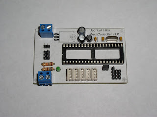
Its a super simple board based around the AVR ATMEGA 644 device. It features only the connections needed for an ax-12 based mech. 5 Ax-12 ports for the four leg and a turret lines, four pin header to attach an xbee explorer board, two three pin headers to digital IO to control dual gun circuitry, separate screw terminals for logic and motor power and an ISP header for programming.
I added 'Faux Silkscreen' by printing out and gluing a sheet of paper with the parts layout and labels onto the ugly fiberglass board.

Friday, January 14, 2011
Trossen Robotics DIY Project Contest #8 Entry
For my entry to the Trossen Robotics DIY Project Contest #8 I have decided to create and document the design of a simple PID velocity DC motor controller. While this idea is not new or novel I feel that many people can take what I have learned from this project and implement it into their own designs. Also this is a project that I can use myself as a component in future robotic projects.

My entry can be found at the following link:
http://upgrayd.blogspot.com/p/pid-velocity-motor-controller.html

My entry can be found at the following link:
http://upgrayd.blogspot.com/p/pid-velocity-motor-controller.html
Subscribe to:
Posts (Atom)